Heat radiometer reference decks
| Component | Radiant heat to a person, reference data for the total-flux heat dose and its INTEGRATED INTENSITY source (#221–#223) |
| Level | FDS case, FDS only: no pyFDS-Evac run |
| Asset | assets/heat_radiometer (_layer, _uniform, _burner) |
| Expected value from | radiation geometry (q/U = 1/4, 1/2, 1) and FDS’s own gauge equations (FDS User’s Guide Eqs. 22.35–22.36) |
| Status | FDS-only reference data; no run reads these decks. The uniform room is the expected value of the f = 1/4 check of the INTEGRATED INTENSITY source (test_heat_integrated_intensity_coupled.py) |
Download the files for this page (13 kB zip)
What is tested
The heat dose has an opt-in total-flux method whose radiant term can come from the FDS integrated intensity U, as f (U − 4σ\(T_s^4\)) with a user factor f (Models › Heat › Radiant flux from INTEGRATED INTENSITY). A radiant term needs the flux that reaches the skin, q, while FDS writes U at a point. These FDS-only decks measure how q relates to U for a skin-like plate at head height, facing up, sideways and down, under a hot layer, in a uniformly hot room and beside a flame: where q sits between U/4 and U, which is the basis for the range of f. The tests check that the decks are set up as described and that FDS’s output obeys the geometry below.
Equations
FDS User’s Guide 6.10.1, Sec. 22.10.12, p. 381. A heat flux gauge at temperature \(T_\mathrm{gauge}\) with emissivity \(\varepsilon\) and convective coefficient \(h\) reads
$$ \dot q''_\mathrm{gauge} = \varepsilon\,\bigl(\dot q''_\mathrm{inc} - \sigma T_\mathrm{gauge}^4\bigr) + h\,(T_g - T_\mathrm{gauge}) \qquad (22.35) $$and a radiometer the radiative part alone,
$$ \dot q''_\mathrm{radiometer} = \varepsilon\,\bigl(\dot q''_\mathrm{inc} - \sigma T_\mathrm{gauge}^4\bigr). \qquad (22.36) $$Both are in W/m² with temperatures in K; FDS writes the device output in kW/m², so the analysis divides \(\sigma T_\mathrm{gauge}^4\) and \(h\,(T_g - T_\mathrm{gauge})\) by 1000. With \(\varepsilon = 1\) the incident flux is \(q = \dot q''_\mathrm{radiometer} + \sigma T_\mathrm{gauge}^4\), and gauge − radiometer = \(h\,(T_g - T_\mathrm{gauge})\). With the gas at \(T_i\) and the gauge at the skin temperature \(T_m\), Eq. 22.35 is the total flux to the skin of SFPE Handbook Eq. 63.49 (5th ed., Ch. 63, p. 2383), \(q = [\varepsilon\sigma(T_i^4 - T_m^4) + h_c(T_i - T_m)]/1000\) in kW/m², with temperatures in K and \(\sigma\) in W m⁻² K⁻⁴, and with the incident radiation taken from FDS’s radiation solution instead of \(\sigma T_i^4\). Both terms are divided by 1000, a decision recorded on Models › Heat › Total flux; the Handbook prints the division on the convective term only.
INTEGRATED INTENSITY is \(U = \int_{4\pi} I\,d\Omega\) (User’s Guide,
p. 403). A flat plate receives \(q = \int_\mathrm{hemisphere} I\cos\theta\,d\Omega\).
From these definitions:
| Field | q/U |
|---|---|
| isotropic, any facing | 1/4 (\(q = \pi I\), \(U = 4\pi I\)) |
| uniform upper hemisphere, dark below, plate facing up | 1/2 |
| same field, vertical plate | 1/4 |
| collimated beam, plate facing it | 1 |
In the ideal layer field (hot hemisphere above, dark below) a plate gets U/2 facing up, U/4 facing sideways and 0 facing down. Only a compact source in direct view drives q towards U.
Expected
From the ideal fields above, at 1.6 m:
| Deck | Facing | Expected q/U |
|---|---|---|
heat_radiometer_uniform | any | 1/4 |
heat_radiometer_layer | up | between 1/4 and 1/2 |
heat_radiometer_layer | sideways (+x, −x) | about 1/4 |
heat_radiometer_layer | down | between 0 and 1/4 |
heat_radiometer_burner | towards the flame | between 1/4 and 1, rising with the flame in direct view |
The real layer is not an ideal black hemisphere and the walls radiate, so the layer ratios are ranges, not exact values; the uniform room is the one exact case.
Setup
heat_radiometer_layer: sealed 4 × 4 × 3 m room, adiabatic on all six faces, 0.1 m cells, four meshes. At t = 0&INITsets gas at 300 °C with soot mass fraction 0.005 from 2.0 m to the ceiling. No fire. 10 s.heat_radiometer_uniform: the same room, all of it at 300 °C with the same soot. The isotropic control. 10 s.heat_radiometer_burner: open 6 × 4 × 4 m domain, a 0.6 × 0.6 m propane burner at 1100 kW/m² (about 400 kW), soot yield 0.01. The +x plates face the flame, whose edge is 0.35–2.35 m from them. 30 s.- Devices, at 1.6 and 1.8 m on a line at y = 2.05 m (7 points in the
rooms, 5 beside the burner), each written per point (
POINTS,TIME_HISTORY=T):GAUGE HEAT FLUX GASandRADIOMETER GASfacing up, +x, −x and down, sharing one&PROP(GAUGE_TEMPERATURE=35, emissivity 1,HEAT_TRANSFER_COEFFICIENT=8);TEMPERATUREandINTEGRATED INTENSITYat the same points;INTEGRATED INTENSITYandTEMPERATUREslices at 1.6 and 1.8 m, both on cell faces. - FDS 6.10.1, four MPI ranks, 100 radiation angles (the default).
Assumptions, not sourced values: the 300 °C gas, the soot mass fraction 0.005, the layer base at 2.0 m, the burner size, fuel, heat release rate and soot yield, the 0.1 m grid, the run lengths, and gauge emissivity 1 as the skin’s emissivity (FDS’s default value, chosen here, not a sourced skin value). The gauge values 35 °C and h = 8 W/(m² K) were chosen for these decks (#224); the skin temperature and h remain open (see Models › Heat › Assumptions). The radiometer, and so q/U, does not depend on h.
Result
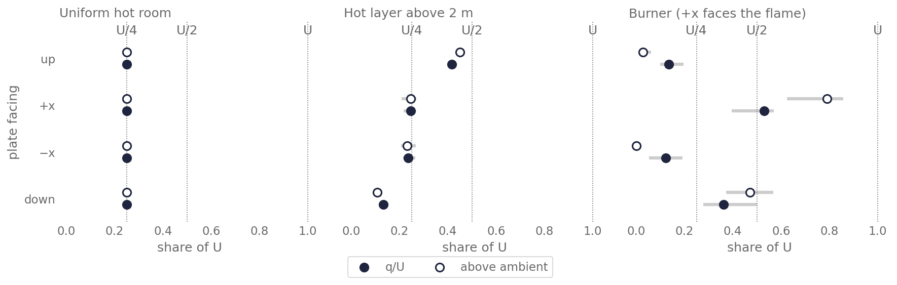
q/U is the time mean over t ≥ 1 s at each point; the table gives the median over the points (min–max in brackets where the points differ). “Above ambient” is \((q - \sigma T_a^4)/(U - 4\sigma T_a^4)\) with \(T_a\) = 20 °C, a ratio defined for this page: it removes the part of q and U that the 20 °C surroundings would give anyway.
| Deck | Facing | q/U, 1.6 m | q/U, 1.8 m | Above ambient, 1.6 / 1.8 m |
|---|---|---|---|---|
| uniform | any | 0.250 | 0.250 | 0.250 / 0.250 |
| layer | up | 0.416 | 0.406 | 0.450 / 0.436 |
| layer | +x / −x | 0.246 / 0.235 (0.21–0.27) | 0.249 / 0.242 (0.23–0.26) | 0.24 / 0.24 |
| layer | down | 0.133 | 0.122 | 0.109 / 0.099 |
| burner | +x, toward the flame | 0.530 (0.40–0.57) | 0.496 (0.38–0.53) | 0.789 (0.63–0.86) / 0.760 (0.60–0.84) |
| burner | −x, away | 0.122 | 0.131 | 0.002 / 0.002 |
| burner | down | 0.362 | 0.375 | 0.470 / 0.516 |
| burner | up | 0.135 | 0.142 | 0.028 / 0.024 |
- Uniform room: q/U = 0.250 for every facing and height: U/4, as for an isotropic field.
- Layer, facing up: 0.41–0.42, above U/4 but short of U/2. Sideways plates stay near U/4, a plate facing down gets less. The lower hemisphere is not dark: the plate facing down still gets 0.10–0.11 of the flux above ambient. A likely cause is the adiabatic floor and lower walls, which re-emit what they absorb; a layer that is not fully black (1 m of soot mass fraction 0.005) may add to it. Neither has been checked.
- Burner, facing the flame: raw q/U is 0.50–0.53, because U still holds the ambient field from all directions. Above ambient, the share is 0.76–0.79 (up to 0.86): q approaches U for a flame in direct view. The time mean includes the first seconds of flame growth; the tests use the last time step.
- 1.6 vs 1.8 m: the medians at the two heights differ by at most 0.04 in q/U.
Other checks on the same output:
| Check | Expected | FDS |
|---|---|---|
| gauge − radiometer − h(T_g − 35 °C), all points, t ≥ 1 s | 0 (Eqs. 22.35–22.36) | ≤ 3.8 × 10⁻⁷ kW/m² |
| largest q/U at any point, t ≥ 1 s | ≤ 1 | 0.25 / 0.46 / 0.70 (uniform / layer / burner) |
| q(+x) + q(−x), largest over points and t ≥ 1 s, over U | ≤ 1 | 0.50 / 0.49 / 0.73 |
INTEGRATED INTENSITY slice against the point device, last step | equal up to interpolation | within 0.9 % (uniform), 2.1 % (layer), 11 % (burner) |
The slice comparison is a one-off check, not part of the script or the tests: the slices lie on cell faces and the devices at cell centres, which matters most in the steep field beside the flame. The point devices are the reference.
Pass criteria
tests/verification/test_heat_radiometer.py:
- Decks. Each deck has the layout above: adiabatic sealed room with a
sooty layer above the devices and no fire; a uniformly hot sooty room; a
burner. Gauges and radiometers at 1.6 and 1.8 m face up and sideways,
share a
&PROPwithGAUGE_TEMPERATURE=35, emissivity 1 andHEAT_TRANSFER_COEFFICIENT=8, and write each point. The slices at 1.6 and 1.8 m sit on cell faces. - Script.
flux_ratioinscripts/verification/heat_radiometer.pyreturns 1/4, 1/2, 1/4 and 1 for the four fields of the table above;excess_ratioreturns 1/4, 1/2, 0 and 1 for a hot isotropic field, a hot upper hemisphere over ambient (plate up and down) and a beam over ambient;summarizereturns the time mean per point, matched by point number, for a synthetic device file. All expected values are written in the test by hand. - Output (skipped when the FDS output is absent, as in CI): gauge − radiometer = h(T_g − 35 °C) to 10⁻⁵ kW/m²; 0 ≤ q ≤ U and two opposite plates together get at most U; in the uniform room q/U = 1/4 and U = 4σT⁴ within ±1 %; under the layer the upward plate gets more than U/4 and more than the sideways plate; beside the burner the largest share above ambient of any plate exceeds 0.5.
The uniform deck deviates from 1/4 by at most 0.3 % (q/U) and from 4σT⁴ by at most 0.2 % (U), so ±1 % leaves room for the ray effect and still fails if σT_gauge⁴ is left out when inverting Eq. 22.36 (about 8 % here). The 0.5 threshold beside the burner and the ±10 % slack on q ≤ U were set from a coarser scratch run (0.2 m cells) before these decks existed.
Run it yourself
The FDS output is not in the repository. Either get it from the project’s
data folder (fds-evac-data/heat_radiometer/{layer,uniform,burner}/), or
rerun FDS outside the repository; the rooms take about 15 s, the burner
about 5 min on four cores:
mkdir -p <data>/heat_radiometer/layer && cd $_
cp <repo>/assets/heat_radiometer/heat_radiometer_layer.fds .
mpiexec -n 4 fds heat_radiometer_layer.fds
# same for uniform and burner
Then, from the repository root:
uv run python scripts/verification/heat_radiometer.py --data <data>/heat_radiometer
uv run python scripts/verification/heat_radiometer_figures.py --data <data>/heat_radiometer
HEAT_RADIOMETER_DATA=<data>/heat_radiometer uv run pytest tests/verification/test_heat_radiometer.py
Limits
- Runs do not read these decks. They are reference data: the
INTEGRATED INTENSITYsource of the total-flux dose is checked against them intests/verification/test_heat_integrated_intensity_coupled.py(#221). Reading gauge devices as an input is not implemented (#276). - A plate is not a person. The gauges are flat, single-sided and fixed in orientation; a body receives flux on many faces at once and moves.
- One set of conditions. One layer temperature, one soot load, one grid, one burner. The ratios under the layer depend on how black the layer is and on the walls; no sensitivity study was run.
- The skin values are open. 35 °C and h = 8 W/(m² K) are the values chosen for these decks, not settled ones. They affect the gauge readings, not q/U.
- Short runs. 10 s in the rooms and 30 s beside the burner; the rooms are sealed and not in steady state, and the burner mean includes its growth.
- The
INTEGRATED INTENSITYslices are written but only compared once to the point devices; the script reads the point devices.