Model elements
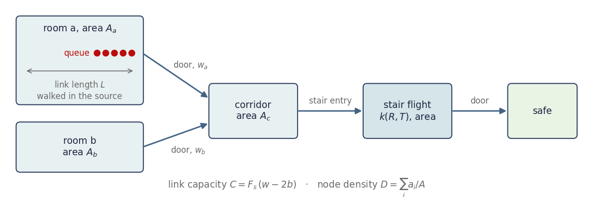
Rooms, corridors and stair flights are nodes, and directed links connect them. An agent walks the length of its next link inside its current node, then queues at the constriction and passes it when the link and the receiving node allow. How to build a network is in Networks; this page gives the relations and the source of each value.
Nodes
A node $n$ has an area $A_n$ and a speed constant $k_n$.
Rooms use the level value $k = 84$ m/min $= 1.40$ m/s [1, Table 67.2, p. 2174].
Stair flights take $k$ from the riser height $R$ and the tread depth $T$:
$$ k_\text{stair} = 51.8\,\sqrt{T/R}\ \text{m/min}, $$the closed form used by EvacuatioNZ [2, §2.1.3, Eq. 2.1; 3, p. 17], which takes it from the New Zealand Fire Engineering Design Guide [18, p. 223]. It reproduces the SFPE stair constants of Table 67.2 [1, p. 2174] to within about 1 % (our comparison). SFPE supports the $\sqrt{T/R}$ dependence only for risers of 165–191 mm and treads of 254–330 mm [1, p. 2175]. For 18/28 cm steps, $k_\text{stair} = 1.077$ m/s.
Safe nodes have an unlimited area. Agents that reach one leave the simulation.
A stair is a node with an area, normally its width times the flight length. Agents on the flight take up space and count towards its density.
Walking speed
The SFPE speed–density relation [1, Eq. 67.3, p. 2174] is
$$ S = k\,(1 - a D), \qquad a = 0.266\ \text{m}^2\text{ per person}, $$valid for densities from 0.54 to 3.8 m⁻². Below 0.54 m⁻² people walk at their own pace [1, p. 2174]. The model takes the density as at least 0.54 m⁻², so the congested speed never exceeds $k\,(1 - 0.266 \cdot 0.54)$:
- 1.199 m/s on level ground, which matches the unimpeded speed of 1.19 m/s in SFPE Table 67.4 [1, p. 2175];
- 0.922 m/s on an 18/28 cm stair.
Each agent walks at the smaller of its own free speed $v_i^\text{max}$ and this congested speed (update scheme). Free speeds above the ceiling have no effect.
Links
A link $\ell$ is a directed passage from a source node to a target node. Its capacity in persons/s is
$$ C_\ell = F_s\,(w_\ell - 2 b_\ell), $$where $w_\ell$ is the clear width, $b_\ell$ the boundary layer on each side and $F_s$ the specific flow in persons/s per m of effective width.
A link also has:
- a length $L_\ell$, the walking distance inside the source node up to the constriction. Both directions of a two-way connection use the same length. On a stair link this model takes it along the incline, since SFPE stair speeds apply along the line of travel [1, p. 2175];
- a merge weight $m_\ell$, the relative share of the link when several links feed the same full node.
Default values and sources
The hydraulic coefficients below are the defaults of
HydraulicParameters, which a study can change per network
(Networks).
Changed values are study assumptions, not validated ranges. The lower
density and the opening boundary layer are fixed.
| Quantity | Value | Source | Code |
|---|---|---|---|
| Slope $a$ | 0.266 m² per person | [1, Eq. 67.3, p. 2174] | HydraulicParameters.speed_density_slope |
| Lower density | 0.54 m⁻² | [1, p. 2174] | hydraulic.MIN_DENSITY |
| $k$, level | 84 m/min = 1.40 m/s | [1, Table 67.2, p. 2174] | HydraulicParameters.level_speed_constant |
| $k$, stair | $51.8\sqrt{T/R}$ m/min | EvacuatioNZ [2, §2.1.3; 3, p. 17] | hydraulic.stair_speed_constant |
$F_s$, door and opening | 1.3 persons/s/m | [1, Table 67.5, p. 2176] | HydraulicParameters.door_specific_flow |
$F_s$, stair | $k/(4a)$; 1.01 for 18/28 cm | derived, see below | hydraulic.max_specific_flow |
$b$, door and stair | 0.15 m | [1, Table 67.1, p. 2174] | HydraulicParameters.door_boundary_layer, stair_boundary_layer |
$b$, opening | 0 m | as EvacuatioNZ enz_opening [3, p. 14] | hydraulic.OPENING_BOUNDARY_LAYER |
| Peak-flow density | $1/(2a) = 1.88$ m⁻² | SFPE gives 1.9 [1, pp. 2175–2176] | HydraulicParameters.peak_flow_density |
| Jam density | $1/a = 3.76$ m⁻² | [1, p. 2175] | HydraulicParameters.jam_density |
max_density | 2.75 m⁻² | EvacuatioNZ default [3, p. 3] | NetworkSimulation |
counterflow | "bounding" | choice of this model (Counterflow) | NetworkSimulation |
routing_policy | "shortest_distance"; "shortest_free_flow_time" costs a link at length / speed(0, k) of the node it leaves | choice of this model, no source (Networks) | NetworkSimulation, network._edge_cost |
| Minimum pass share $y_0$ | 0.17 | adapted from [21, p. 36] | simulation._COUNTERFLOW |
| $g_0 \to g_{1/2}$, door and opening | 0.84 → 0.94 (bounding), 0.90 → 1.00 (estimate) | walkway data [21, Table III, p. 36; 22, p. 4; 28, Fig. 6; 31, p. 11-7; 24, p. 1613; 23, p. 44] | simulation._COUNTERFLOW |
| $g_0 \to g_{1/2}$, stair | 0.75 → 0.94 (bounding), 0.80 → 1.00 (estimate) | [29, p. 520; 24, Fig. 3, p. 1615]; $g_{1/2}$ = 0.94 from walkways | simulation._COUNTERFLOW |
The stair specific flow is the maximum of the SFPE specific flow
$F_s = (1 - aD)\,kD$ [1, Eq. 67.6, p. 2176], reached at
$D = 1/(2a)$. SFPE tabulates this maximum (Table 67.5) but does not
write it as $k/(4a)$. The formula reproduces the table to rounding, for
example 1.08/1.064 = 1.015 against 1.01. For door links the code uses
the tabulated 1.3 instead of the level-ground maximum of $1.40/1.064 = 1.32$.
Agents
A population places agents in a start node. Each agent $i$ has
- a free walking speed $v_i^\text{max}$,
- a pre-movement time $t_i^\text{pre}$,
- an extra start distance $s_i$,
- an area factor $a_i$. A value of 1 stands for an average adult.
The area factor scales the agent’s contribution to the persons/m² density of the SFPE relation. It is a choice of this model and is not calibrated. SFPE notes that the hydraulic model does not consider body size [1, p. 2185]. The published approach to mixed body sizes is the Predtechenskii–Milinskii dimensionless density, with its own speed and flow curves [1, pp. 2185–2187]; the area factor is not that method.
Routes
Each agent follows a fixed route to the nearest safe node, measured by
default as the sum of link lengths; routing_policy="shortest_free_flow_time"
measures it as the sum of length / speed(0, k) of the node each link
leaves. A population with a target heads for that
safe node instead. One shortest-path table is computed per target before
the run starts. Details and the handling of ties are in
Networks.
Choices of this model
Where the model departs from the SFPE hydraulic model
The SFPE hydraulic model counts people, not individuals, and gives all of them one set of movement attributes [1, p. 2185]. This model adapts it as follows:
- Individual agents. Each agent has its own free speed, pre-movement time, start distance and area factor.
- Free speed and congested speed. An agent walks at $\min(v_i^\text{max}, k(1-aD))$. Combining the two is not part of SFPE.
- Area factor. See Agents.
- Stair speed. The closed form $51.8\sqrt{T/R}$ comes from EvacuatioNZ, not from the SFPE chapter, and is used for any step size.
- Stair specific flow. $k/(4a)$ is computed from the stair geometry instead of read from SFPE Table 67.5.
- Opening. The zero boundary layer of
openingfollows EvacuatioNZ; SFPE gives 0 only for theatre chairs and stadium benches [1, Table 67.1, p. 2174]. - Door specific flow. 1.3 persons/s/m from SFPE; EvacuatioNZ uses 1.33 by default [2, §2.2].
- Densities above 1.88 m⁻². SFPE states that densities above
1.9 m⁻² should not be assumed in engineering designs
[1, p. 2175]. The whole range between the peak-flow
density and
max_density, including the supply reduction, is a choice of this model. - Passage time. A fresh link, or one idle for at least $1/C$, lets the first agent through at once, so the last of $N$ agents passes after $(N-1)/C$. SFPE gives $N/C$ [1, Eq. 67.9, p. 2177] (update scheme).
- Counterflow. SFPE has no counterflow term. The two links of a two-way connection share one door; their total $g(s)\,C$ is a linear interpolation between anchors from walkway and stair data (Counterflow).